
FG6020 Duct Temperature and Humidity Transmitter with 4-20mA Output

Measure air temperature and relative humidity and send separate 4–20mA signals to compatible controllers or data acquisition equipment. FG6020 combines a flange-mounted probe with a 12–36V DC supply and DIP-switch temperature range selection.

  • Separate temperature and humidity current signals for compatible analog input channels.
  • 12–36V DC power supply for equipment integration.
  • Flange mounting for positioning the probe in a duct or air measuring location.
  • Selectable temperature measuring ranges to match your application.
4–20mA
Analog current outputs
12–36V DC
Power supply
Flange
Duct mounting configuration

Confirm that your receiving equipment supports the required current inputs. Match its wiring and measurement scaling to the transmitter configuration.

Request a Quote

Include your required measuring range, receiving equipment, quantity and delivery country.

Specifications & Flange Installation

Check the current outputs, supply voltage and measuring ranges against your receiving equipment and installation requirements.

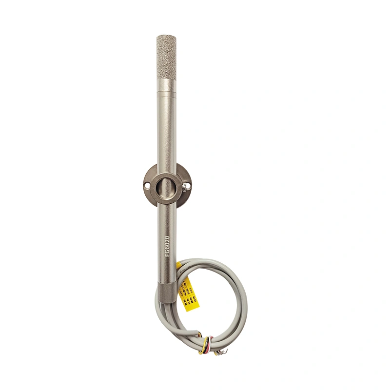
FG6020 analog current output transmitter, flange-mounted configuration.
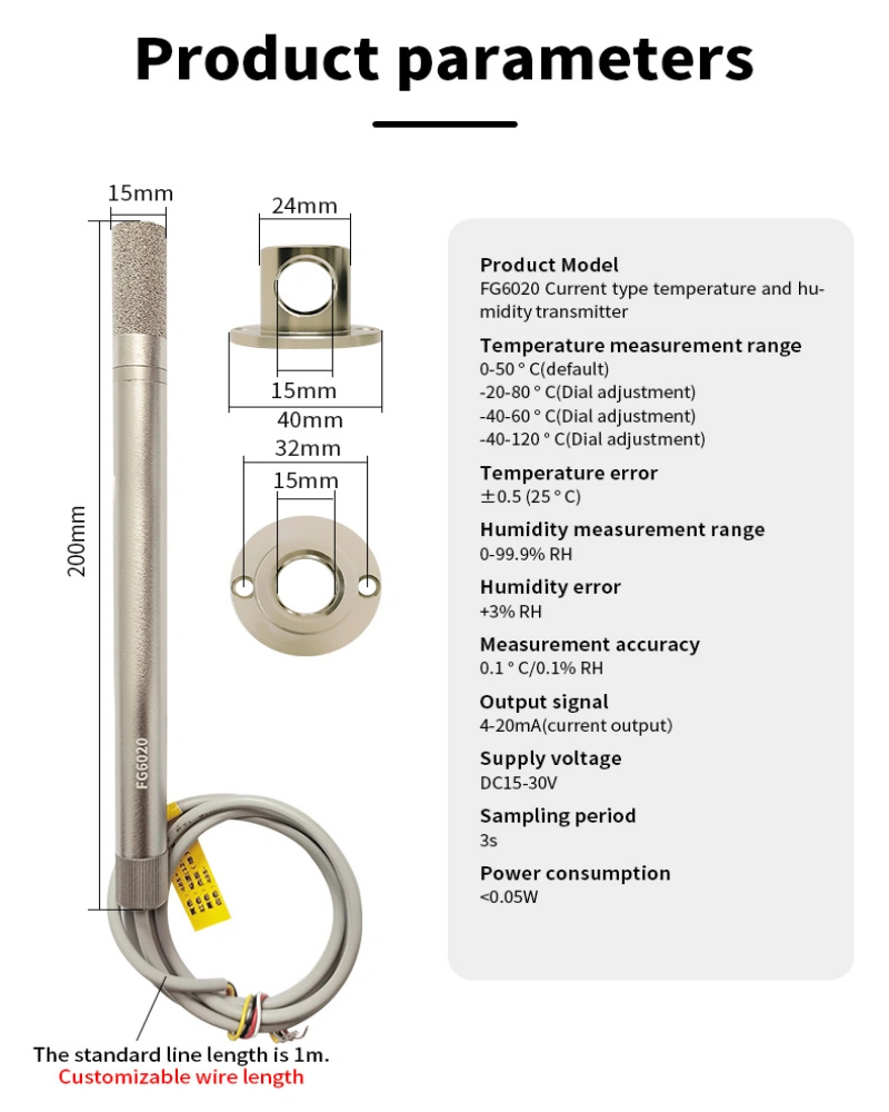
Specification FG6020
Measured parameters Air temperature and relative humidity
Output type Analog current signals
Output signals Separate 4–20mA outputs for temperature and humidity
Power supply 12–36V DC
Selectable temperature ranges
0 to 50°C — default −20 to 80°C −40 to 60°C −40 to 120°C
Temperature range selection DIP switches
Humidity measuring range 0–99.9% RH
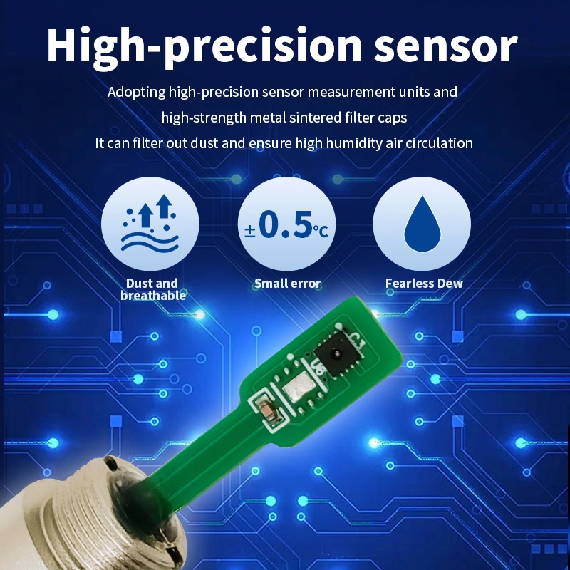
Temperature accuracy ±0.5°C at 25°C
Humidity accuracy ±3% RH
Temperature resolution 0.1°C
Sampling interval 3 seconds
Standard cable length 1 m
Installation Flange mounting

Configure the receiving equipment for 4–20mA inputs and match its temperature scaling to the selected measuring range. Follow the FG6020 wiring diagram for the power and signal connections.

FG6020 technical graphic showing probe dimensions, mounting flange dimensions and transmitter specifications
Open full-size drawing ↗

Probe & Mounting Flange

Check the probe and flange dimensions against your duct opening, insertion position and available installation space.

Mounting
Flange-mounted probe
Sensing point
Probe tip exposed to the air being measured
Cable route
To the DC supply and compatible current inputs

Position the sensing end in representative airflow. FG6020 measures air temperature and humidity; do not immerse the probe in water.

Connect the Current Outputs and Set the Range

Identify the power and signal leads, then configure the receiving equipment for the transmitter's 4–20mA outputs and selected measuring range.

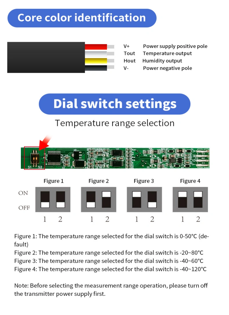
FG6020 cable wire identification and DIP switch diagrams for temperature range selection Open full-size wiring and switch diagram ↗
Refer to the diagram supplied with your unit for wire colors and DIP switch positions.
01 / Electrical Connections

DC Supply and Two Current Signals

FG6020 uses a 12–36V DC supply and provides separate 4–20mA signals for temperature and humidity. Use compatible current input channels on the receiving equipment.

Supply positive
Connect to the DC supply positive terminal.
Supply negative
Connect to the DC supply negative terminal. Follow the transmitter and receiving equipment diagrams for signal return connections.
Temperature output
Connect to a compatible 4–20mA input channel for temperature.
Humidity output
Connect to a separate compatible 4–20mA input channel for relative humidity.
02 / Range and Input Scaling

Match the Controller to the Selected Range

The DIP switches select the temperature measuring range. Set the corresponding measurement scaling on the receiving device.

  1. Select the required temperature range using the switch diagram before powering the installation.
  2. Configure the receiving channels for 4–20mA current input.
  3. Match the temperature channel to the selected temperature range and the humidity channel to the specified humidity range.

Example: With the transmitter set to 0–50°C, configure the temperature channel for a 4–20mA input representing 0–50°C.

Air Measurements for 4–20mA Input Systems

Supply air temperature and relative humidity measurements to compatible current input channels on controllers, PLCs and acquisition equipment.

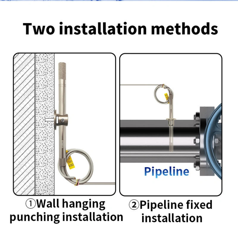
FG6020 installation illustration showing probe mounting through a panel and into an air duct
Air measurement installation illustration. Check the flange position, probe insertion and available cable route for your equipment.
Duct Air Measurement

HVAC & Ventilation Ducts

Mount the probe through the duct wall to measure temperature and humidity at the sensing point. Choose a position with representative airflow and check the available insertion depth and flange mounting space.

Equipment Integration

Air Handling & Ventilation Equipment

Provide separate temperature and humidity current signals to a compatible equipment controller. Select the temperature range for the air conditions being measured and match the controller's input scaling.

Analog Current Inputs

PLCs & Data Acquisition Equipment

Use separate compatible 4–20mA input channels to read temperature and humidity. Confirm the input module's wiring requirements, signal return connections and the available DC supply before selecting the configuration.

Frequently Asked Questions

Answers about current outputs, receiving equipment, measuring ranges and flange installation.

Does FG6020 provide both temperature and humidity outputs?

Yes. FG6020 provides separate 4–20mA current signals for air temperature and relative humidity. Reading both measurements requires two compatible current input channels on the receiving equipment.

Can FG6020 connect to my PLC or controller?

It can connect to equipment with compatible 4–20mA analog inputs. Confirm the input module's connection requirements, signal return wiring and available supply against the FG6020 wiring diagram.

Send us the exact controller or input module model if you need help checking compatibility. The 4–20mA signal specification alone does not determine the complete wiring arrangement.

What is the difference between FG6020 and FG6010?

FG6020 provides 4–20mA current outputs. FG6010 provides analog voltage outputs, with 0–10V as the standard configuration and 0–5V available on request.

Choose the output type that matches your receiving device's inputs, then check the supply, wiring and measurement scaling.

How do I select the temperature measuring range?

Use the DIP switch positions in the wiring and range selection diagram . Available temperature ranges are 0–50°C, −20–80°C, −40–60°C and −40–120°C, with 0–50°C as the default setting.

Configure the receiving temperature channel for a 4–20mA input and the same selected temperature range.

Can the probe measure water or other liquids?

FG6020 measures air temperature and relative humidity. Position the sensing end in the air being measured; do not immerse the probe in water or other liquids.

If your installation is exposed to condensation or direct spray, describe the conditions so we can check suitability before you order.

How is this configuration installed and powered?

This page shows the flange-mounted configuration, powered by a 12–36V DC supply. Check the probe dimensions, duct opening, insertion position and available flange mounting space before installation.

Route the cable to the supply and receiving inputs according to the supplied wiring diagram.

Request a Quote for FG6020

Need a flange-mounted temperature and humidity transmitter with 4–20mA outputs? Tell us about your application so we can confirm the measuring range, equipment compatibility, pricing and shipping options.

Include these details if available:

  • Receiving equipment: The controller, PLC or input module model, or its 4–20mA input specifications.
  • Measurement and power: Expected air temperature and humidity, and your available DC supply voltage.
  • Installation: The duct or equipment location, mounting requirements and cable length needed.
  • Quantity and destination: How many FG6020 units you need and the delivery country.

Not sure whether it matches your equipment? Describe the application and share the receiving device's input specifications. We can help check the product requirements and confirm suitable options with the supplier.

This field is required.